
Wiring Installation of Single Phase 120V & 240V Circuits & Breakers in Main Service Panel
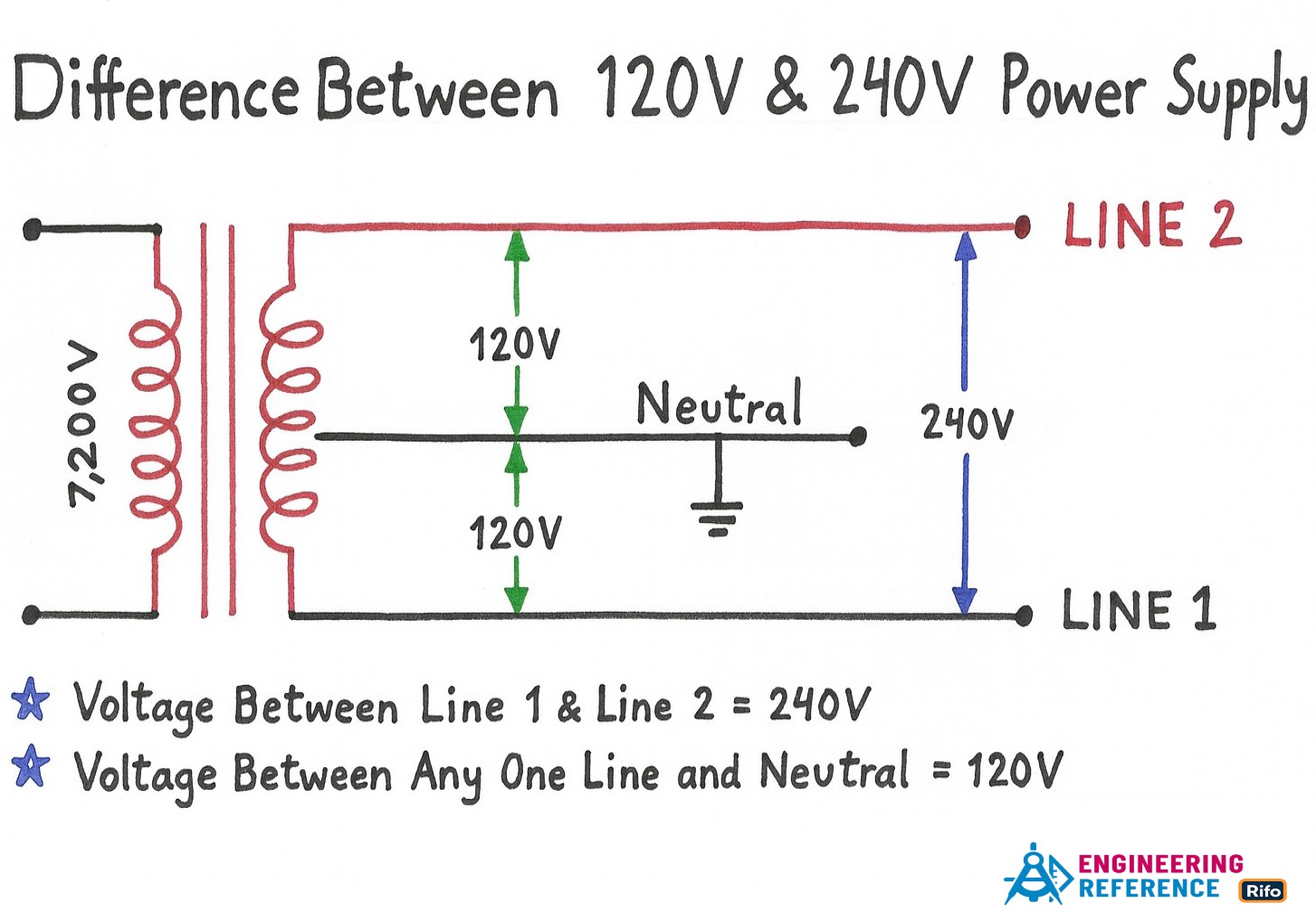
In the USA and Canada, homes follow the NEC and CEC electrical standards. A neighborhood transformer usually receives 4.5 kV to 7.2 kV on the primary side and then steps this voltage down to 120V single-phase and 120/240V split-phase power for houses. The primary side of the transformer is fed by two conductors: a high-voltage line and a neutral. You can think of this step-down process like a gear system that reduces speed but increases usable force.
The secondary winding of the transformer has a center tap, which creates three output wires: Hot 1 (Line 1), Hot 2 (Line 2), and Neutral. The voltage between either hot conductor and the neutral is 120V, which is used for standard household circuits. The voltage between the two hot conductors is 240V, which powers larger appliances. Both outputs are still single-phase, but Hot 1 and Hot 2 are 180° out of phase, so the difference between them adds up to 240V instead of 120V.
These three wires enter the meter box and then continue into the main service panel. In this tutorial, we explain how to wire 120V single-phase and 240V split-phase circuit breakers and loads inside a typical residential main panel. The goal is to help you understand where each conductor goes, why the connections matter, and how the breakers manage and protect each circuit.
Inside Main Breaker Box
The figure below shows a typical breaker panel used for 120V and 240V circuits. Three conductors enter the main panel from the meter and the main disconnect:
-
Hot 1 (Line 1) = Black
-
Hot 2 (Line 2) = Red (for illustration only)
-
Neutral = White

Hot 1 and Hot 2 are firmly attached to the lugs of the main circuit breaker. These lugs stay energized at all times, even when the main breaker is OFF, so they should never be touched under any condition.
The main breaker sends power to the two hot busbars inside the panel, shown as black and red for clarity. Each busbar carries 120V, and the voltage between them (Hot 1 and Hot 2) is 240V. This is how a split-phase system provides both standard outlets and higher-voltage appliance circuits.
The white neutral conductor connects to the neutral busbar, which remains at 0V. This neutral bar is bonded to the grounding busbar for safety, and the grounding bar also stays at 0V. All metal parts of the enclosure must be properly grounded according to NEC rules.
In this setup:
-
Voltage between Hot 1 and Neutral: 120V (single phase)
-
Voltage between Hot 2 and Neutral: 120V (single phase)
-
Voltage between Hot 1 and Hot 2: 240V (split phase)
-
Voltage between Neutral and Ground: 0V
For 120V single-phase circuits, a single-pole breaker connects one hot busbar (Hot 1 or Hot 2) to the neutral. For 240V split-phase circuits, a two-pole breaker connects to both hot busbars to deliver the full 240V.
Warning: Never touch the terminal screws above the main breaker. They remain energized whether the switch is ON or OFF.
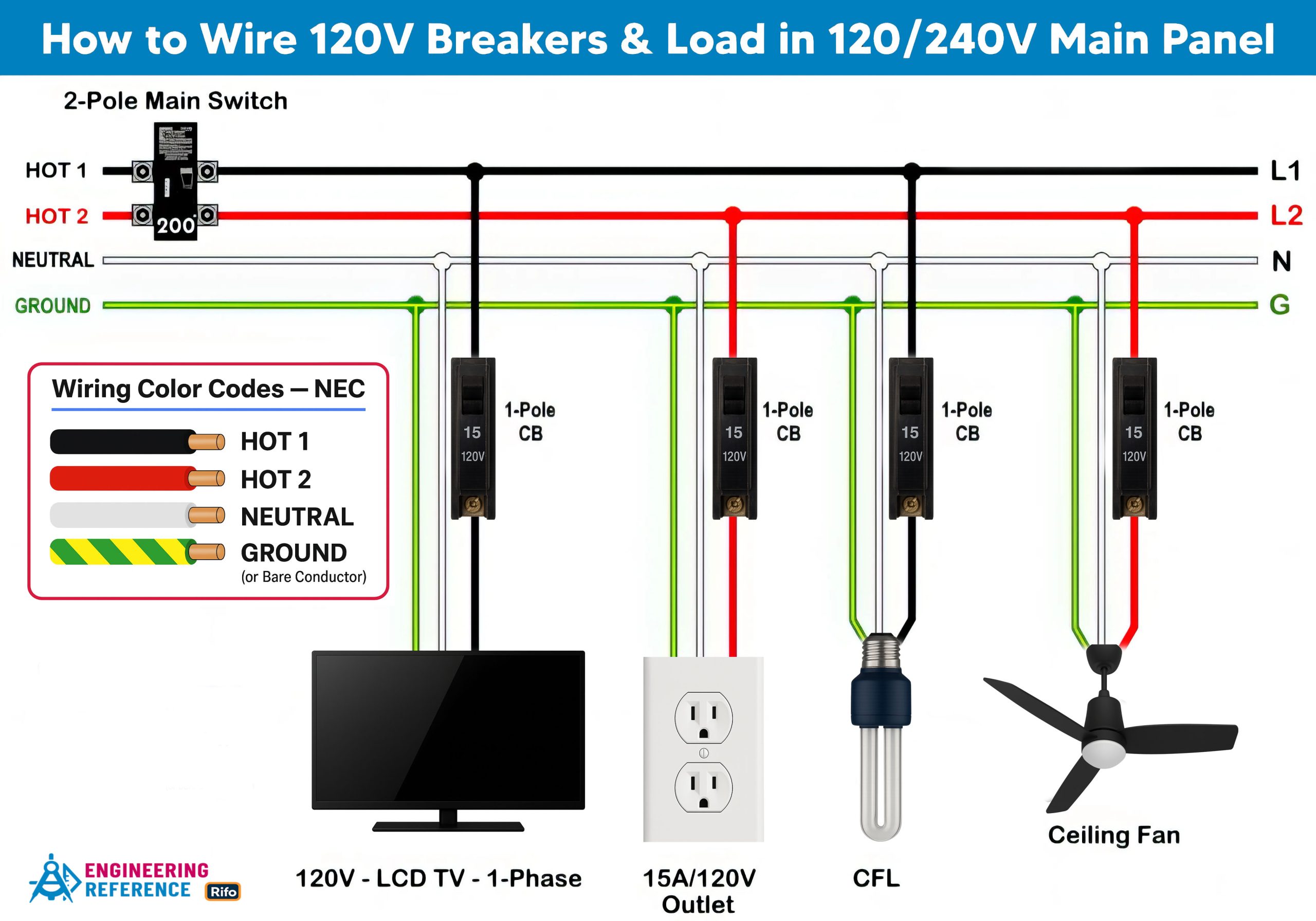
The figure below shows a typical main service panel with 120V and 240V single-phase/split-phase wiring and breaker installation.

How to Wire 120V Circuits & Breakers
The following tutorial explains how to wire a 120V single-phase breaker and its load points inside a residential panel. These circuits are commonly used for lighting and standard receptacle outlets, making them some of the most familiar wiring tasks in a home.
To set up a 120V single-phase circuit, install a single-pole 15A or 20A breaker on either hot busbar (Hot 1 or Hot 2). The metal mounting tracks in the panel hold the breaker in place and allow it to connect properly to the energized busbar. Once the breaker is mounted on Hot 1, for example, its output terminal feeds the load using a black hot conductor.
In a typical setup, the breaker’s output wire (black) connects to the ceiling fan. The fan’s neutral wire (white) goes to the neutral busbar, and the bare copper or green/yellow grounding conductor attaches to the fan’s grounding terminal. For ON/OFF control, a single-pole wall switch must be placed only on the hot conductor—never on the neutral—to ensure safe operation and proper disconnection.
Use #14 AWG for a 15A breaker and load, and #12 AWG for a 20A breaker and load, according to NEC Table 310.16, NEC Table 210.24(1), and NEC 240.4(D)(6). A 20A receptacle is allowed only on a 20A breaker, and should never be installed on a 15A circuit. Under NEC 210.19(A)(1) and NEC 210.20(A), breakers must be sized at 125% of continuous load, meaning a breaker should carry no more than 80% of its rating. For example, a 12A continuous load belongs on a 15A breaker, while a 16A continuous load requires a 20A breaker, which can supply up to 20A for non-continuous use.
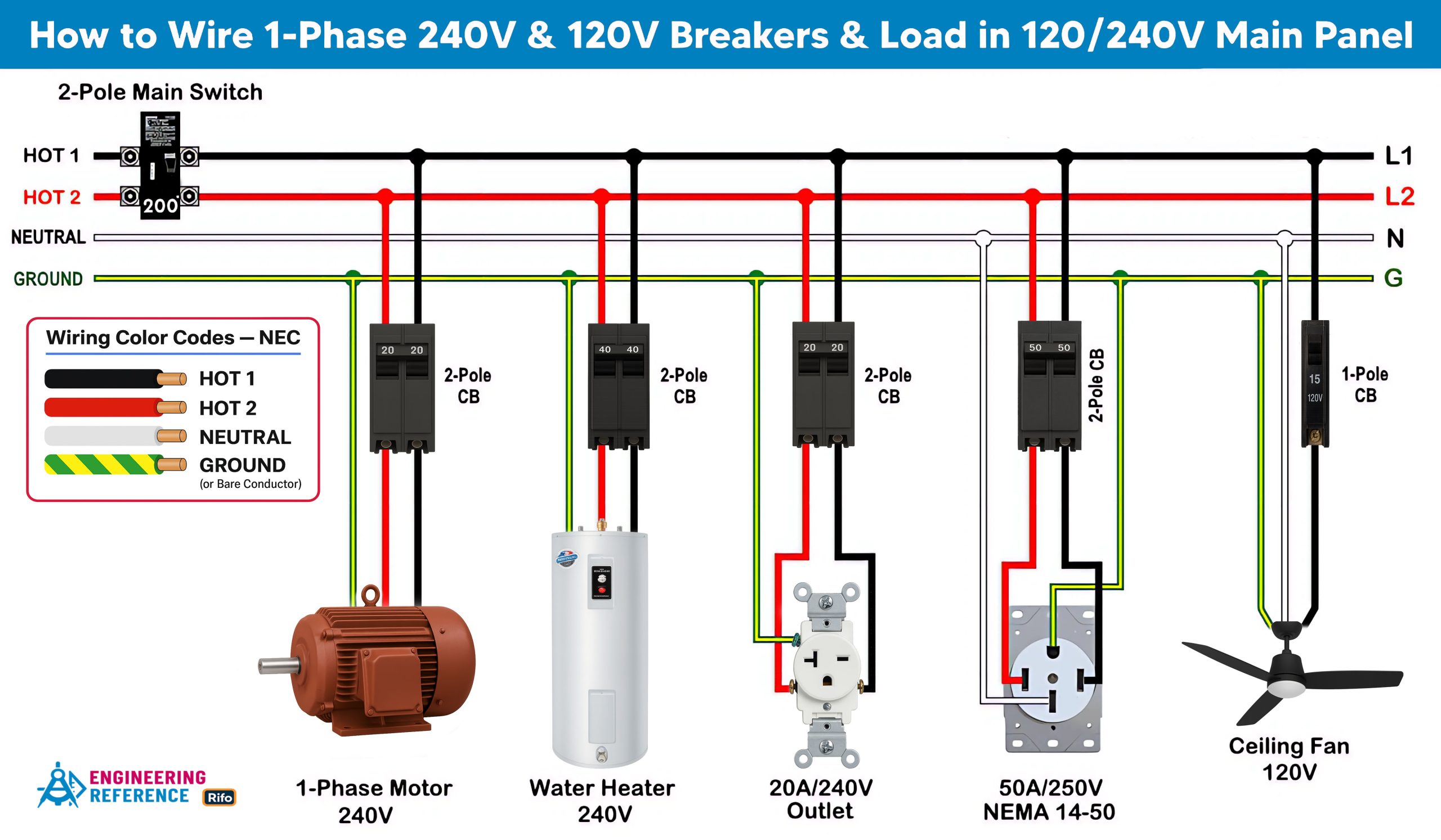
How to Wire 240V Circuits & Breakers
The following tutorial explains how to wire split-phase (240V single-phase) circuit breakers and their load points inside a residential distribution panel. These 240V circuits are usually dedicated lines meant for high-power appliances such as dryers, ovens, washing machines, air conditioners, water pumps, and motors.
To install a 240V circuit, mount a two-pole breaker onto the panel’s metal tracks so it locks onto both hot busbars at the same time. The breaker rating must match the needs of the appliance. The two output conductors from the breaker connect directly to the load, and a bare or green equipment grounding conductor (EGC) connects to the appliance’s grounding terminal. The correct EGC size can be found using NEC 250.122 and Table 250.122.
In standard 240V split-phase circuits, a neutral conductor is not required for appliances that only need hot-to-hot voltage, such as NEMA 6-15, 6-20, 6-30, and 6-50. However, some modern appliances need both 240V (hot-to-hot) and 120V (hot-to-neutral) connections. These use receptacles such as NEMA 10 series or NEMA 14-50/14-60 for EV charging and other mixed-voltage loads. Always check the appliance manual or manufacturer details if you are unsure.
Never use mismatched breaker ratings, such as putting a 30A breaker on a 15A, 20A, or 40A outlet or load. The same 125% continuous-load rule applies to 240V circuits, meaning the continuous load must not exceed 80% of the breaker rating. For example, a 30A two-pole breaker may safely supply up to a 24A continuous load.
As per NEC Table 310.10, the following wire sizes (copper recommended) must be used with single-pole or two-pole breakers and their load points:
-
15A Circuit = 14 AWG
-
20A Circuit = 12 AWG
-
30A Circuit = 10 AWG
-
40A Circuit = 8 AWG
-
50A Circuit = 6 AWG
-
60A Circuit = 6 AWG
-
70A Circuit = 4 AWG
-
80A Circuit = 3 AWG
-
90A Circuit = 2 AWG
-
100A Circuit = 1 AWG
-
125A Circuit = 1/0 AWG
It is also against code to use two separate single-pole breakers to supply a 208V or 240V circuit unless they meet certain conditions. If two single-pole breakers must be used, they must have a common trip or handle tie so they turn ON and OFF together, they must have matching amperage ratings, and they must be installed on opposite busbars (Hot 1 and Hot 2). If both breakers sit on the same busbar, the appliance will receive only 120V instead of 240V, which can cause malfunction or damage.
Good to know: Four conductors (Hot 1 + Hot 2 + Neutral + Ground) are required for grounded 125/250V single-phase circuits, plugs, and outlets, including NEMA L14-30R, L14-20R, 14-60R, 14-50R, 14-30R, 14-20R, and 14-15R receptacles.
Wiring Color Codes
This tutorial uses NEC and common practice wiring color codes. Always follow the National Electrical Code and any color-code rules required in your region or by local authorities.
-
Black = Hot 1 or Line 1
-
Red = Hot 2 or Line 2
-
White = Neutral
-
Green or Bare Copper = Ground (EGC)
For 240V systems, the recommended hot conductor colors are Black and Red, though both conductors may be Black if needed. If a white wire is repurposed as a hot conductor in a 240V circuit, it must be re-identified with black tape or a black marker at both ends to show that it carries voltage and is not a neutral.
Never use green, green/yellow, or bare conductors for any wire that carries voltage. Use copper wire only in the main panel to reduce resistance and heat. Aluminum conductors should not be used for these critical connections.
Safety Precautions
Disconnect the power source—and verify that it is truly OFF—before servicing, repairing, or installing electrical equipment. Always switch OFF the main breaker in the panel. This step is critical for preventing shock or arc flash injuries.
Never touch the screws above the main breaker. These terminal screws stay live at all times, even when the breaker is OFF. Avoid touching wet surfaces or exposed metal parts while working on energized circuits, as this greatly increases the risk of electric shock.
Carefully read and follow all safety instructions related to this tutorial or any electrical task. Always use the correct wire gauge, proper outlet and switch ratings, and the correct breaker size. A wire and cable size calculator can help you choose the right conductor for your circuit.
Do not attempt electrical installation or repair without proper knowledge and supervision. Work should always be performed under the guidance of a trained and qualified person. In some areas, doing electrical work yourself can be dangerous and may even be illegal. When in doubt, consult a licensed electrician or your local power utility before making any wiring changes.
The author is not responsible for any loss, injury, or damage caused by improper use of this information or incorrect wiring practices. Electricity is extremely dangerous, so stay alert and use maximum caution at all times.


